Month: March 2011

  • Back to basics…the 74HC04

    I love blinky things and I love to think about how to design something a little differently.
    Probably the most common way to control red-green-blue LEDs is with a pulse width modulation signal from a microcontroller. Many coding interfaces have built in PWM functions so that you can be up and running within a few minutes or hours.

    But what if you don’t want to write software? Or you don’t want to deal with buying a whole other set of tools, programmer, microprocessor, cable… and then you have to download a compiler too. Instant gratification, NOT.

    All this just to make a blinky.

    I am making an RGB LED fader that can be controlled without software or a microprocessor.
    When you use a hex inverter of the 74 series, a 74C04, you can make it oscillate simply by tying the output to the input.

    Update: I couldn’t get the 74C04 to oscillate, but had great success with the 74HC14

    There are 6 inverters on my 74C04 chip, but an RGB LED only has 3 distinct LEDs in it.
    Here is what a “typical hex inverter oscillator” using 1 inverter looks like:
    f
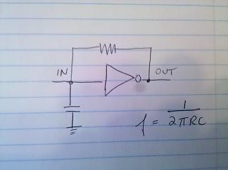
    I’m going to run the 3 oscillators through an LED. Basically, I’m going to connect one end (the common anode) of the LED to the +Voltage and the other 3 pins (red, green, blue) through resistors to the outputs of the inverter.

    A small word about 4-pin common anode vs. common cathode LEDs:
    Be careful what you buy. If you buy the common cathode version, you need all of your control lines (red, green, blue) to be controlled by sourcing current. Since many LED drivers sink current it may be better to purchase a common anode RGB LED from which the control lines can be controlled from ground. I have 32 common cathode RGBs lying around. Sigh.


  • Voltage and Current RMS rambling

    An easy way to calculate the power needed to drive the speaker uses Paverage = VRMS * IRMS, or Paverage = Power (Watts) = Voltage squared/ Resistance (Ohms). This uses only the resistive part of the impedance.

    Watts RMS actually doesn’t exist. The voltage in the formula refers to RMS Voltage (explained below), but the calculated power is average power and it is called Watts.

    AC Voltage and Current cycles from 0 to the positive peak voltage, and back through 0 to the negative peak voltage. Since it isn’t accurate to get the voltage or current value by measuring AC Voltage at an instantaneous point, RMS is used as a way to define the effective value of an AC (changing with time) voltage or current.
    RMS is not the average, the average of an AC signal is zero because the negative and positive peaks cancel each other out.
    V RMS is = 0.7 * Vpeak
    Vpeak is = 1.4 * VRMS

    Here is a good way to picture it : A lamp connected to a 6 VDC shines with the same intensity as a lamp connected to a 6 VRMS supply. If you connect the lamp to a 6 Vpeak supply, then it is only getting 0.7 *6 VRMS = 4.2 VRMS (same as 4.2 VDC). This example came from here.

    A DVM shows VRMS values on the digital readout. This is useful because it makes a nice comparison to a DC Voltage such as for a battery.
    An oscilloscope shows the entire cycle, and exhibits the Voltage peaks, both negative and positive.


  • Loudspeaker ramblings

    I’ve never really thought too much about getting sound out into the world. Everything just…works. I have an old Samsung mp3 player, it plays music through speakers into my ear. I can adjust the volume easily.
    Same for my beloved Droid phone. It outputs both music and voices.

    Last summer I built something that ran off a 12 volt -12 amp-hour battery. The sound output was through an 8 ohm speaker. Not only was the sound not very loud, but the battery ran flat after 2 nights.
    Oops.

    I will take the opportunity for a do-over! I know- very exciting….SPEAKERS!!!! Amplifiers!!!! Noise!!!!
    A little research turned up the following: speech is at 60 dB, vacuum cleaners at 70 dB and a chainsaw is 110 dB.
    And over 192 dB can kill you. WTF????

    For what I’m doing, I’m OK with vacuum cleaner loudness, so I would design for 90 dB to give some space above what I need.

    In order to figure out my power calculation (so that I don’t end up with dead batteries this summer) I need to know what my power calculation in Watts is, as it relates to dB.
    Looks like I need about 4 – 8 Watts of power to run my speaker, depending on the type of speaker.

    A speaker isn’t completely a resistive load -the value of a speaker is measured in inductance, which varies with frequency and resistance. The impedance of the speaker is related to the frequency. The graph below illustrates an 8 ohm speaker as it relates to frequency. I think this graph is interesting. It clearly shows that 8 ohms is an average and the impedance of the “8 ohm” speaker is all over the map.

    amp