Back to basics…the 74HC04
I love blinky things and I love to think about how to design something a little differently.
Probably the most common way to control red-green-blue LEDs is with a pulse width modulation signal from a microcontroller. Many coding interfaces have built in PWM functions so that you can be up and running within a few minutes or hours.
But what if you don’t want to write software? Or you don’t want to deal with buying a whole other set of tools, programmer, microprocessor, cable… and then you have to download a compiler too. Instant gratification, NOT.
All this just to make a blinky.
I am making an RGB LED fader that can be controlled without software or a microprocessor.
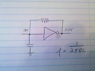
When you use a hex inverter of the 74 series, a 74C04, you can make it oscillate simply by tying the output to the input.
Update: I couldn’t get the 74C04 to oscillate, but had great success with the 74HC14
There are 6 inverters on my 74C04 chip, but an RGB LED only has 3 distinct LEDs in it.
Here is what a “typical hex inverter oscillator” using 1 inverter looks like:

I’m going to run the 3 oscillators through an LED. Basically, I’m going to connect one end (the common anode) of the LED to the +Voltage and the other 3 pins (red, green, blue) through resistors to the outputs of the inverter.
A small word about 4-pin common anode vs. common cathode LEDs:
Be careful what you buy. If you buy the common cathode version, you need all of your control lines (red, green, blue) to be controlled by sourcing current. Since many LED drivers sink current it may be better to purchase a common anode RGB LED from which the control lines can be controlled from ground. I have 32 common cathode RGBs lying around. Sigh.