Month: December 2011
-
Cell phone signal detection part 3
High frequency signals are so mysterious! How to design PCBs around them, how to detect the signal, how to usefully process…
I’ve ordered some building block parts to string together a detection circuit in the 700MHz to 2.8GHz frequency range. I’m starting with an evaluation board from Analog Devices.
I decided to go with an evaluation board because I’ve heard all sorts of dire warnings about board layouts making your circuits not work. On every chip manufacturer site (ie: Analog, Maxim etc.) there is a nice tutorial about PCB layout for RF PCBs.
I also ordered a quad band antenna from Spark Fun, which I’ll try and directly couple to the eval board. If the signal is too low, I’ve ordered an RF amplifier to raise it up.
I’m excited! Stay tuned…
Link to the first post in this series
Link to the second post in this series -
Cell phone signal detection part 2
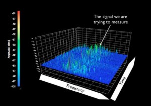
From some of the emails I’ve gotten, and recent conversations I’ve had, it is clear that many of us are curious about how to characterize, decode or simply identify the level of cell phone signal power/radiation.
Wikipedia says typical cell phone transmission power is in the 125mW to 500mW range.
I grabbed this picture from Peter Cochrane’s blog to illustrate how small of a signal this is.
The circuit I’m working on simply detects (a power level) when a call, text or email is made.
It uses an antenna to detect the signal, which attaches to an RF detector to output a power level. Basically these chips are little power meters. Unfortunately, they are only available in surface mount which is a total pain in the ass for prototyping, and even more annoying for designing an easy to assemble kit.
Most of the RF detectors go to an input level of -60dBm, which means an amplifier will be required in between the antenna and the RF detector. Typical opamps don’t have the required frequency response, so a specialized RF amplifier is the type of amplifier needed.A huge shout-out to Analog Devices for their help in understanding these concepts. They also have some really informative presentations on their site.
Linear Technologies has some great information as well as having a super easy sample policy. My itty bitty chips just arrived, for free, via Fedex. Thanks Linear!RF “stuff” is really, really interesting to me. I think this is because the signals are truly invisible (to me) because I don’t have the tools needed to “see” what is going on. Other kinds of invisible signals can easily be viewed on an oscilloscope, even though understanding what is seen is another story 😉
Signal Hound’s Spectrum Analyzer : WANT!
See the post before this one: Cell phone signal detection part 1
Link to the third post in this series