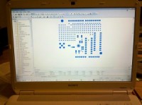
Soldering Surface Mount – QFN adventures
I recently designed my first RF signal detector circuit and PCB layout. There’s all kinds of RF layout warnings out there.
“It won’t work if you lay out your board wrong”
“You’ll have to troubleshoot invisible wireless signals with no spectrum analyzer.”
“How are you going to solder that itty bitty QFN package crucial to the design?”
Telling me I can’t do something is sure to make me see it as a challenge.
So I got a couple of experienced people to look over my layout, who encouraged me to make changes and I sent it out. It turns out that an RF layout is quite important, you can put unwanted inductances (signal strength suckers) and not enough ground shielding into your circuit, causing what you thought was a nice design to … well, not work.
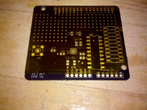
After my layout drama was resolved, I sent my Gerber files to Laen’s PCB service which cost me around $25 for 3 boards.
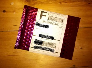
The boards came back in a sparkly purple envelope, graded.
Since the boards from Laen include silkscreen on both sides, I put a nice Lex Kravitz original drawing on the back of my board.
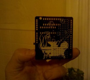
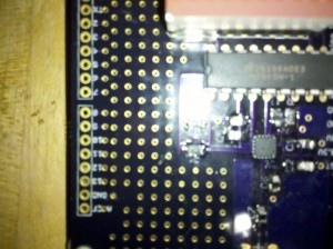
There is a QFN-16 part on the front of the board. QFN stands for Quad-Flad No Leads. That means there are no leads to solder to as they are conveniently placed UNDER the chip like a chastity belt.
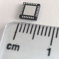
This picture is of a 28-pin QFN.
The only way to get at these leads is to reflow solder, or put solder paste onto the PCB and plop the part on top, hoping that the solder will find its way to the leads and not bridge or leave any leads out.
So I put my newbie questions out into the Twitterverse.
“What tools should I use for reflowing?”
“What solderpaste and flux should I buy and from where?”
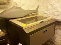
Here is the reflow tool that was recommended.
I bought all my flux and pb-free solder paste from SRA. They’re on the east coast (USA) and so am I, so the shipping time was fast, although they charged me $8.50 for a ton of paper packaging. So they get an “FAIL” for environmentalism. Not cool.
My husband, Oliver Tanner is a 3D designer and mechanical prototype machinist, so he has all kinds of fun tools like a laser, lathe and CNCs (yes plural). Ollie offered to cut me a stencil on the laser. The idea here is that you cut a stencil, squeegee solder paste through the holes, put the part on top and reflow. This isn’t exactly how I did it sucessfully, but almost.
Our first try was with Kapton 2″ tape.
I found the Kapton difficult to work with, too sticky, too thin, not wide enough (my board is 2.3″ wide), so we tried cutting again with an Avery label.
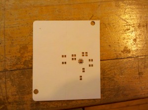
The cutting came out pretty well this time, and the Avery label, being 2x thicker than Kapton, peeled nicely, and by now I’d peeled a stencil on and off half a dozen times and was feeling like this was cake. The following is a fast-forward to the successful method through the first 4 tries of getting the part to land correctly.
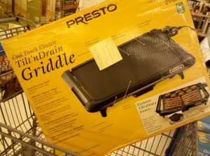
After squeegee-ing the solder paste through the holes, I placed my board on the griddle at 325 degrees F and let the solder flow. Note: At this time there is NO flux on the board at all. In fact, I cleaned the board with 90% alcohol using a Q-tip before putting the solder paste on.
I then put another Avery stencil on the board and dripped some flux through the stencil and just on the solder paste. This was very difficult to do as flux is like water and just wants to go everywhere. I was getting a lot of bridging until I reduced by 4x as much flux as I thought I should use.
I took the QFN-16 part and placed it gently on the area, lining up the unseen leads as best as I could. You can see a glint on the top of the chip of where the leads are, so it’s not totally blind. In the future, I will make the QFN leads on the PCB a bit longer so that there is a clearer placement.
Then I put the board back onto the griddle at 350F and waited about 5 minutes to remove the board.
It did take 4 tries, but after checking connectivity on all 16 pins, this one was down.
The real proof was after I hand soldered all of the 0805 (measures 0.08 by 0.05 inches) capacitors and resistors, the circuit works without getting hot or smoking or sadly refusing to accept power. YEAH!