For the purposes of my project I am defining cell phone signal detection as a change in power level sensed at the frequency of the cell phone. I am not doing any decoding of signals and there is no jamming (although I fully support projects of this type), I am only detecting a very small signal.
From searching online, I notice a common frequency among US-based cell phones- the 850MHz band and the 1900MHz band. Each cell phone company has its own special frequency to broadcast on. For example, (I read this at RF Solutions) Sprint Nextel channels are scattered between 806 to 821, and then 851 to 866MHz. So Verizon, AT&T etc. won’t be on the Sprint bands. Have something to add to this? Please comment below.
As I’ve mentioned in the posts before this one, my circuit is based around the AD8363 from Analog Devices. I’ve learned in the past week or so that basing my circuit on this chip alone isn’t going to amplify the cell phone signal sufficiently (sensitivity) or do the frequency filtering for me (selectivity).
I need to filter out FM Radio (up to ~140MHz) and TV broadcasting stations (~470MHZ and up to 806MHz). Using the AD8363 requires some filtering on the input, because the chip itself is capable of sensing from 50Hz up to 2.6GHz. On the low end, I put a basic high pass filter in series between the antenna and the input. This cuts off lower frequency signals below about 700MHz.
Here’s a picture of a passive high pass filter. The R here represents the AD8363, which happens to be 50ohms. I know this because the datasheet told me so. The Vout is the filtered signal that goes into the RF detector. The RF detector has 2 RF inputs, one where the signal goes in and the other connected to ground.
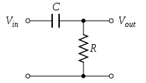
The formula for the capacitor is Frequency in Hz= 1/(2 × π × 50 × C). What this capacitor will actually do is reduce the power going into the AD8363 below the calculated frequency, rendering the AD8363 useless at those frequencies.
One issue I have with this chip is that it will only detect to about -56dBm. The transmitted cell phone signal is actually about -60dBm or less. I also want my circuit to work from an 8′ distance so this requires an amplifier before the detector.
SIDE NOTE: DBm is means the power ratio in decibels (dB) of the measured power referenced to one milliwatt (mW). I keep looking at this great table on Wikipedia to get a sense of what that means in real life. My phone actually has a reading of its own received signal power and it is in the -88dBm range!
While visiting GigaHertz LLC last week, I had the opportunity to work with their spectrum analyzer. So I actually got to see what frequency my phone was working (about 840MHz) on as well as the transmitted power (-65dBm). Verizon phones apparently hop frequencies depending on location so it was fun to see what my phone was transmitting on in Pittsburgh.
I neglected to take any photos of the spectrum analyzer’s screen, but I found something at 911 Dispatch that illustrates the idea.
What you see with the spectrum analyzer is the frequency (x-axis) vs. amplitude (y-axis). This is exactly the tool needed to characterize the cell phone signal to be detected.
This has been a really long post, so if you got this far, thanks for reading. At some point, I’ll talk about the amplifier that was selected (recommended by GigaHertz) and some of the different antennas I’ve been testing with. Oh, and how to cut the upper frequency off before it reaches Wifi (2.4GHz).
Link to part 5 in this series
Link to part 4 in this series
Link to Diode Detector post
Link to part 3 in this series
Link to part 2 in this series
Link to part 1 in this series
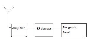
This is a block diagram that shows the basics of the circuit: