Cell phone signal detection part 4
20 days until Spring! This has been the suckiest winter ever for snowboarding, I haven’t gone even once. It snowed today and I just didn’t feel like it.
Instead I’ve been procrastinating with a Mindbands brainwave detector.
Last week I re-spun my cell phone signal detector board in two different versions, both to include smaller traces on the QFN (easier to reflow without shorts!). One of the versions has a power supply right on the board, the other uses an Arduino. The new spin moves the LEDs out of the way so that they aren’t switching on and off right next to the detector part of the circuit.
RF engineering is its own special brand of difficulty. At times I’m really discouraged, nothing seems to work and I don’t understand why.
So while I’m waiting for my boards to arrive in mid-March, I’m re-reading the RF detector chip documentation from Analog Devices. My circuit is based on the AD8363 and that will certainly change. The chip is fairly expensive and the range is too wide. I’ve been looking at some Mini Circuits chips because they’re cheaper and have a smaller range. I’d really like to detect up to 2GHz, and not have my circuit blinking about and confused because of random Wifi in the neighborhood.
You can think of an RF detector chip like a little power meter. It takes in RF signal on one end from the antenna’s output and gives out a DC voltage. The voltage is proportional to the received signal (Watts). Pretty cool. You can then take that DC voltage and “do stuff” with it.
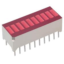
I’m running a bar graph with it, so the higher the voltage received, the higher the LEDs on the bar graph light up.