Blog

  • Hacking at Sparkfun Electronics

    I’m working at Sparkfun for a couple of weeks, as a Hacker-in-Residence.
    Link to nice post Sparkfun put on their blog about the program.

    Sparkfun is a great place to work. Besides all of the hardware available to build with, there is a large (and very smart) engineering team to work with.
    There are also people to bounce new product ideas off of. YESSSSSS!
    At home, I mostly work by myself and it can be isolating. By contrast, having people to interface with is enjoyable….and it makes the design process easier.

  • HeartBeat Boombox at NYC World Maker Faire 2013

    For World Maker Faire 2013, I made a heartbeat-activated boombox. The photo on the previous page is the improved version of this project- the tech is the same, but I added a laser cut facade to bring to FITC Toronto and the NYC Resistor Interactive Show.
    There are three medical-grade (meaning: expensive and accurate!) pulse oximeters which people can use to control three separate drum sounds, a snare, maracas, and a Djembe. An pulse oximeter sensor has a fantastic user interface, you simply put your finger into the clamp and the oximeter starts to read both pulse (units: beats per minute) and blood oxygen saturation (units: percentage).
    Most people intuitively know how to use the pulse oximeter sensor, no explanations necessary.

    Me and my brother Lex Kravitz at Maker Faire
    DSC_0192_2


    The boombox itself is made by SONY. I designed a board that interfaces with the hacked pulse oximeter. The pulse ox has a beeper on it which I removed and then tapped into the beep output. The beeper beeps with the user’s heartbeat so this works great.

    The pulse ox interface board controls three separate sound cards which contain the drum sound and three individual LED-reel circuits. I use sound cards from Electronics 123 as they are USB programmable and have pretty good sound quality. I removed the push button on-off switch and used a transistor to drive the sound card. The interface board is basically an Arduino, as I used the part of the Arduino that has the Atmel 328 and changed the power supply a bit to allow for increased power draw.

    I used the AVRISP mkII programmer to work with the Arduino’s IDE over ICSP. I’m horribly out of practice with writing software so using the Arduino’s IDE was super easy.
    I also put an LED driver on my board- it’s over-engineered, using a Mosfet that allows for 2 Amps, when the LEDs draw less than 1/2 an Amp!
    Here’s the schematic HB Boombox2

    I had this as a walk-around project (rather than being at a booth), so I used batteries to power the project. My biggest mistake was using Li-Ion batteries with JST connectors. The Li-Ion batteries ran out of charge after about 4 hours. The connectors fell off easily and were difficult to solder back on. I WILL NEVER USE JST CONNECTORS AGAIN!

    I spent a ridiculous amount of Maker Faire time in the Radio Shack booth! Radio Shack was awesome though, they had a table in the back with a soldering iron and a never-ending stream of kids who played with the powered parts of the boombox. I’d be soldering one pulse-ox and two kids would be playing with the other two. The other thing was that people don’t like being around charging Li-Ion batteries. People kept asking me if the charger was safe and if it had built in protection. I assumed that it did, but I didn’t know for sure, so that made me really uncomfortable, just walking away while my batts were charging.
    The sound luckily was powered by 6 D-size batteries that came in the boombox and it was nice and loud!

    Best moment at Maker Faire was seeing my 9 year niece, Kaylee. She and two other young girls played the boombox for an annoyingly long time, but she turned to me and said incredulously “You made this?”.


  • Cell Phone Signal Detector Schematic!

    I get so much email about this circuit that I’m going to post it here as jpg.  Here are the files, schematic and PCB, in Kicad.

    If you use these files, please turn the silkscreen layer on because I didn’t and so my boards didn’t have any. Also, please credit me for the design work. Don’t be pissed off at me if you can’t get what you want out of this design. It detects a voltage potential from 8′ away. The QFN is a PITA to solder but you can get free samples from Analog Devices. I got pretty good at soldering these after I blew up 6 of them.

    Finally, use these and make it better!

    Printing Print Schematic

  • What I’m working on right now 9/9..Maker Faire

    http://mix-engineering.com/wp-content/uploads/2013/09/HB-Boombox1.pdf

  • Open Hardware Summit!

    I am going to the Open Hardware Summmit tomorrow!
    It has been held in New York City in the past, and always around the same time as Maker Faire NYC. The location and my addiction to Maker Faire made it really easy for me to attend the past 2 years.
    This year, the Open Hardware Summit is at MIT, in Boston. Not such a huge deal, it’s a 4 hour drive, and I get to check out Artisan Asylum!

    Also- this year I am a speaker at the summit! I will be presenting a (very) short talk about Market Analysis….and also as part of my talk, showing off my FISH TRAINING project.


    Unfortunately, that project died in prototype land, but that’s what I’m going to talk about.

    I have a long history of chasing dreams, and specifically, dreams that involve complicated, time consuming and expensive engineering. I look back on the past several years and realize I’ve designed many products for companies that got canceled or just plain sucked. The reason that any of these projects even got as far as me working on them was because the due diligence in the form of a simple market analysis was never done.

    So that is what I am going to talk about- how to look objectively at a project and do a short formulaic analysis to see if there is any point in making it. And of course, there is ALWAYS a point to making something for the sake of making it, it is just when the point is to make money that it’s necessary to evaluate first.

    Looking forward to seeing everyone!

  • Hacking a Digital Scale

    My brother Lex works in a lab with a lot of mice. Some of the people who work there have a job weighing mice.

    The mice need to get weighed everyday, I guess their weight is one way to tell the scientists if they are healthy or not. There are many, many mice in labs and people spend a lot of time weighing them.

    We thought a small inexpensive digital scale to put in each mouse-house would be great! The scale could log the weight of the mouse every time the mouse jumped onto it.

    This scale was purchased on Amazon for about $8.

    IMG_20130806_163959_103


    I proceeded to take it apart, exposing the goodies within. The electronics aren’t very interesting, a blob hiding something or other which talks to an Atmel Serial EEPROM. There are also some capacitors and resistors and a nice LCD screen on the front.

    IMG_20130806_164959_418


    But actually….in order to hack into the scale, I don’t care about all of that. The only thing I need from this assembly is the scale, that is, the weighing piece. It’s called  a strain gauge. This post- is in progress. Check back!

    IMG_20130806_165042_760

  • DIY EDM Machine

    My husband Ollie decided to build an Electric discharge machining (EDM) machine a couple of months ago.

    EDM machining is a process where a shape is obtained from a piece of metal by using sparks to remove material! If you have a shape that you wish to reproduce-you make a copper positive of the shape you wish to reproduce (hereafter called the electrode), and by passing a high voltage spark between the electrode and the process material (will become the finished part), erode the process material to exactly match the shape you want.

    This book by Ben Fleming is really well written and has great schematics and explanations for how the circuitry works. If you’ve ever had to trace a circuit with a highlighter and a red pen in order to analyze how a circuit is supposed to work, the explanations are appreciated.

    There’s a lot going on in this project with high voltages, indicator dials, AC, DC and signals. The brain of the whole thing…

    (drumroll)

    The 555 timer.

    IMG_20130601_101750_345

    Ollie’s EDM machine is coming out really well.

    IMG_20130601_102116_379

    Here is the electrode in the chuck. My cell camera didn’t pick up the sparks, but the electrode is sparking a deep hole in the process material in this photo.

    IMG_20130601_120015_015

    Today we went to Ollie’s workshop to tune the spark timing.

    On the front of the machine, there are two dials, one for ON time and one for OFF time. They work independently of each other. They are wired to the R1 and R2 on the 555 timer chip for asynchronous control.

    We used the scope to see how fast the spark was across the gap in the electrode and the process material when it was doing the best job of removing material.

    IMG_20130601_115858_124


    It seemed like it was on the order of a few microseconds (as in…under 4)! As we turned the ON and OFF times to different values, at times, the electrode shorted completely to the process material.

    Altogether, a very impressive project!


  • THE HUNGRY, HUNGRY FISH

    I’m working on a new art-engineering project with my brother Lex. It’s a Secret Project so I won’t say too much. The project has to do with fish, and making the fish do our bidding. Jump through hoops fish, jump!

    The first fish, Goldie, died just a few days after she came home. She wasn’t very excited by food, so she was probably sick to begin with. I was strangely depressed over her death, even though she lived and died in another city, and I never even got the opportunity to know her.

    Lex just came home with new fish!
    Check out the video of Goldie II and Goldie III – right-click and save as wmv in order to view.

    The Hungry Fish small

  • Oscilloscopes -Part 1

    Hello-
    It’s been nearly 3 months since I last posted (bad, distracted, Sophi), and I went back and forth about whether or not to post about my new Art project (hint: it involves temperature control and major logistics) or Engineering.

    I’ve decided to write about one of my most useful lab tools, the oscilloscope. An oscilloscope lets you see invisible electrical signals, usually showing how they change over time. The X- axis is time (inverse of frequency) and the Y- axis is amplitude. Other useful things an oscilloscope will show you is how much noise there is in the area of interest, how much of the signal is AC or DC and if your component is not working.

    Actually seeing if your component is not working at all is pretty easy- just put the scope on the output and see if anything happens. It’s way more annoying when the component is working just a little bit and puts out an unclear signal.

    Photo of a Teledyne LeCroy oscilloscope –
    for the purpose of the photo, it’s showing a calibrated 1kHz signal from the scope itself.

    Typically, modern oscilloscopes are digital oscilloscopes. Old oscilloscopes are analog. Simply put, this means that analog oscilloscopes display the original signal and that digital oscilloscopes process the signal from analog to digital. There’s tons of information out there about the differences between them. Let us know in the comments if you find some interesting trivia!

    There are a few specifications to look for when buying an oscilloscope, over the next few posts, I want to discuss the following: bandwidth, sampling rate, triggering, memory. We’ll also discuss probes and the different kinds you can get. I’m going to be visiting a lab next week where they look at picoVolts and they use special probes for less noise.

    I bought my first oscilloscope off of eBay for $140 in 2006. It’s an analog oscilloscope and made by a company called SPECO, which I’m not even sure if it exists anymore. It also looks like I may have paid too much- as I wrote this post, I looked for a link to it, and you can now buy it on eBay for $35.

    You’ve heard the expression you get what you pay for?
    In the case of the cheap SPECO, it’s true.

    The SPECO has a bandwidth of 20 MHz, the LeCroy pictured above has a bandwidth of 200 MHz! I also have another oscilloscope made by OWON that has a bandwidth of 60 MHZ.

    The ultimate goal is to get your input signal represented accurately on the screen of the oscilloscope! So you need to choose a scope with a bandwidth large enough to show your signal range. So what does bandwidth mean exactly in the context of oscilloscopes? What can you even look at with such a small bandwidth of 20 MHz? What kinds of signals need the resolution of 200 MHz?

    Bandwidth is defined as the frequency at which a sinusoidal input signal is attenuated to 70.7% of its original amplitude. This is also called the -3 dB point. At the -3 dB point, the signal of interest will start to distort so you need to choose your scope so that it has a frequency range large enough to not lose any signal amplitude.

    I’ve seen a number of slightly different recommendations around- but most online recommendations agree that buying an oscilloscope with bandwidth with at least 5 times the highest frequency component in your signal will achieve good results. If I want to look at a signal of 40 MHz, then the LeCroy oscilloscope pictured above is a good choice. If I am only going to look at signals to troubleshoot if a switch is on or off, then a lower bandwidth oscilloscope is fine.

    Some of the signals I look at are:
    RF detection chips– low MHz to GHz! Needs a high bandwidth oscilloscope like the one in the picture above

    555 timer signals– microseconds/ high-KHz, low MHz! Can get by with the Owon, although I would never recommend that oscilloscope to anyone. After I wiggle some wires around, I can get good results with my analog scope too.

    PIC Microprocessors– nanoseconds/ high MHz Needs a higher bandwidth oscilloscope

    That’s it for today- my next post will discuss sampling rate and what it means.
    What kind of oscilloscope do you have and more practically, what kind of signals are you looking at?

  • The Super Green Dot Project

    Hello!
    Update:
    I’ve started a new website, which is keeping me very busy. It’s a website about working for yourself, with interviews with people who have left their “Job” or “Career” and are happy doing what they do now.
    It’s called The Super Green Dot Project and I hope that you’ll check it out!

    ~Sophi

  • Cell Phone Signal Detector – Part 7, transmission line width… and KiCAD!

    I made a couple of PCB versions of a cell phone signal detector and my board layout didn’t work as well as my evaluation board.


    Thanks to Daryl Mitchell for the photo

    For a long time, I thought it was because I was home-reflowing the QFN chip.

    Recently, I had the opportunity to talk to people who do RF layout. It was then that I was introduced to the concept that a 4 layer board will require a much thinner transmission line (for a matched 50 ohms) than a 2 layer board.
    My RF circuit requires 50 ohms for the best power transfer between the antenna and the rest of the circuit. You can read more about impedance matching on Wikipedia, but the basic idea here is when the antenna and the circuit have the same impedance, it is like a seamless wire. Ideally, you want your power source, transmission line and load to match, otherwise … it won’t work!

    Unmatched impedances will cause your input signal to attenuate in power by varying degrees depending on how bad your impedance match is.
    This concept is one of the first things I learned in Electromagnetics class in school, but there is no substitute for learning like hands-on!

    There are a number of transmission line calculators online. I chose the one from EE Web. I think it’s pretty clear from the diagram what the inputs mean, but just quick: the trace thickness is the thickness of your trace. You get this from the weight of your PCB. OSH Park, where I get my boards fabbed, has 1 oz copper on the top layer. My transmission line is on the top layer, which is 1 oz copper. Substrate height is the height between the bottom the trace to the next layer. Trace width is what controls the transmission line impedance, so you have to change this until your output reads the desired impedance. And the substrate dielectric is also available from your board house. It’s the Greek symbol εr and it means relative permittivity.

    The width of my needed transmission line on a 4-layer board turned out to be 0.03mm. On a 2-layer board, the transmission line size needed is 3mm. I decided to go with a 4-layer board on my next round. My PCB layout software is a lite version of Eagle ($70), but Eagle doesn’t allow 4 layers with this version. I could pay $169 for a Hobbyist version which includes 6 signal layers, but I sell boards. The standard is $820, which is still an excellent price, considering many PCB software packages are thousands.

    KiCAD is an open source, free software that allows multiple layers. For this circuit, it turned out to be an obvious choice. I learned enough of the software to make a board within 2 weeks, and
    sent it off to be fabbed. I am impressed with how intuitive KiCAD is to learn, and will continue to use it on all of my boards that require more than 2 layers.

    Link to part 6 in this series
    Link to part 5 in this series
    Link to part 4 in this series
    Link to Diode Detector post
    Link to part 3 in this series
    Link to part 2 in this series
    Link to part 1 in this series


  • A personal post + blogging at Engineer Blogs

    Hello!
    I’ve been writing over at Engineer Blogs since February 2012. I’ve written 7 posts so far.
    As I blog at EB more, my plan is to focus more on writing about Making Time For Projects
    and Creating Freedom-based Income 🙂


    Thanks to Jeannie for the photo

    My thoughts and ideas on this are many, and I write for those who have already found their passion. In my case, my passion -electronics and product design- cannot be shaken. Each day comes with a burning to solve a problem, create a new product, finish a project or in rare cases, clean up my shop.

    I have gotten several emails from people who question how I have time to make so many projects.
    So how am I doing this?

    After working as a Design Engineer for several years, I came to the realization that no one would ever hire me as an engineer with a flexible schedule, or for less than 50 (60?) hours per week. A Design Engineer job means you belong to the company that hires you. In return, you get a sweet salary, health insurance, 2 weeks of paid vacation and some sick time. Plus retirement money in many cases.
    I decided to take a chance, jump out of Engineering and into in Sales, where I work about half-time. The schedule is more flexible simply because I’m dealing with people all over the world and in different time zones. I gave up the health insurance (I pay for my own) and the 2 weeks paid vacation (I take as much unpaid vacation as I want).
    I am lucky to pick up freelance design work on the side and have recently started Marketing consulting for New Products. Want to hire me? Email Me

    So if you’re in an job and desperately want to have time for your own projects or start a business, going part time is an excellent option. You don’t completely give up your income, which is helpful. If your job won’t let you go part time or flex-time, then you have to look for one that will- or switch fields. It’s a definite risk AND you have to find the part time job that pays enough to pay your bills.
    I will reach my 2 year anniversary of Not Working Full Time at An Engineering Job on July 2nd. I think these have been the best two years of my life so far.

    UPDATE: My sister Ana Kravitz has a Analytical Marketing Consulting practice for website analytics and she is called MIX Analytics!

  • Mouse Nose Poke! An IR Beam-Break circuit

    Scientific research mice are often trained behaviorally by giving them treats as rewards.
    Some Neuroscience students that I met recently train their mice by giving the treat when they poke their noses into an area of the enclosure they are running around in.


    The area contains an IR emitter and receiver. When the mouse pokes its nose into the area, it breaks the beam and some kind of treat is delivered.
    The idea is to take data on how desperate the mouse is to get the treat, whatever that may be. In some cases they are studying the effects of drugs, and in other cases, the effect of food.

    The students had a small issue, their Nose Poke module plugs into a larger instrument, that collects data and does a bunch of other stuff. Unfortunately, since it’s part of the larger system, the Nose Poke module needs 28V to work.

    All they need for many of their experiments is a Nose Poke that puts out an active high or low that runs on 5V. In fact, because of the difficulty in interfacing with the larger instrument, their rig to get to 5 Volts is complicated and is prone to mechanical error.

    Today, I started building them a simple 5 Volt Nose Poke system that they can easily add into their existing data collection system.
    I started at my favorite store, Radio Shack. Radio Shack is the only local place around here that sells components. They pretty much have most of the basics and for $3.79, I walked out with part number 276-0142, Infrared Emitter and Detector. With 2 resistors and a display LED to show that the circuit is working, I came up with this circuit:


    When you put your finger in between the Emitter and Detector, the display LED (the red one) shuts off.


    It was good to run a quick test on the circuit- I hadn’t specc’d IR components before and Digikey (my next stop after Radio Shack) provides many options. I wanted to get a sense of the important specifications to shop for. It is clear that the further away the emitter and detector are from each other, the more power is needed. By the way, the 100 ohm resistor that I used in the above circuit for the Emitter makes a nice bright beam but gets hot (and its a 1/2 Watt). Using more resistance didn’t allow the Emitter to provide enough power to get to the Detector.

    Next steps: choose parts and design PCB.

    Thanks to Rick Eh? for the mouse photo


  • Texting Trapper at Maker Faire 2012

    This year, Ollie Tanner and I brought the Texting Trapper project to the Bay Area Maker Faire.

    Update: This project was in the MAKE: Blog … Hooray!
    I’m also in a Maker Faire after party video (around 8:13) from Dangerous Prototypes

    The Texting Trapper is a product that detects when people are texting. It is used in the classroom or conference room to indicate when someone is using their phone when they are not supposed to be!
    The Texting Trapper is a 3.5 inch diameter attractive-looking hemisphere. It glows in increasing brightness as the power levels change.

    Ollie and I brought a blown-up version of this product to get some Market and Technical research from a large crowd with different cell phone providers and cell phone models. Our blown up version is a bar graph which bounces up and down with the cell phone signal levels.

    The 8′ bar graph is being triggered by a child texting the sensor circuitry in the globe.

    Since the idea of the product is to detect transmitted and received signals from a good distance, I made sure that there would not be any cell towers too close to the Maker Faire site ahead of time. It was fun looking at maps of where cell towers are located!
    Unfortunately, since cell service where Maker Faire is located (San Mateo fairgrounds) is poor, a temporary tower was brought in, and placed very close to the building we were exhibiting in.

    Check out the cell tower serving up extra radiation!


    After setting up the exhibit, we realized that it was full on all the time, the cell tower was overpowering the exhibit and we weren’t going to be able to show anything except a big, red, bright light.
    Not only that, my circuitry was now getting hot since it was designed for pulsing high amps but not running 13 amps through the circuit all the time. UGH.

    My new friend Álvaro Prieto made shorter antennas out of solder and tried to fix the situation with the one 5dB attennuator I had brought with me. No joy at all. Over dinner after setup, my friend Pete Doktor suggested we put tin foil around the exhibit to block the cell tower. I laughed at the low-tech suggestion but my wheels were turning. My brother Lex Kravitz, who is one of my favorite project partners, then suggested we build a Faraday cage around the sensor circuitry to keep out the cell tower. He works in a lab that happens to have Faraday cage materials lying around.

    Here’s Ollie and Lex making the cage on Saturday morning ONE HOUR before Maker Faire opened.


    And here’s what it looked like during the fair. Not bad, eh?


    We put my cell phone under the Faraday cage and told people to text the project. Over the course of the weekend, we received over 400 texts!

    I’ve had a few email questions about how Ollie built the bar graph to diffuse the light so well, so I’ll detail how he did this in another post.


  • The Texting Trapper

    Oliver Tanner and I are exhibiting the Texting Trapper at Maker Faire Bay Area this upcoming weekend. The Texting Trapper is a large scale exhibit which detects the strength of your cell phone.
    Oliver designed and fabricated the 8 foot tall VU meter. It’s made from 8′ tall aluminum, which he welded into custom extrusions to hold eight 8″ x 24″ pieces of white acrylic.
    Here it is in the light:


    And here it is in the dark (yes, that’s Oliver):


    I made the LED panels from reels of LEDs. It was a lot of work, but The Buessli helped me!


    I spent days troubleshooting a really annoying issue. When the whole thing was set up, the 10th panel (at 8 feet up) was noticeably less bright than the others. In fact, it drew only 0.44 Amps, while the 1st panel (2 feet up) drew a full 1.08 Amps. The 3rd, 4th,…8th, 9th panels also got increasingly less bright and drew less Amps as they got further away. The first troubleshooting direction I went in was line losses. This brought me to charts and wire gauge inspection – I’m using 18 AWG – and to a number of sites about 12V lighting schemes which said beware of the line loss problem.
    I was almost convinced except that 18 AWG loses 1.27 Volts over 100 feet. Even with the extra back and forth of making the panels, I had at most 30 feet of wire. It just didn’t make sense. I then took the whole thing out of its nice acrylic frame and laid it all out on the floor. I measured a 4 Volt drop at the 10th panel! Well, this didn’t make sense at all. After a couple of people insisted that I need to use heavier gauge wire, I swapped out the 10th panel’s 18 AWG for 12 AWG. No joy.
    I texted my friend Jon and he suggested that my power supply was bad. After going through THREE power supplies that did not meet specification (they did not have the Amp draw advertised on the label), this was determined to be the problem as they stopped producing power at 3 to 5 Amps.
    IT PISSES ME OFF HOW MUCH TIME I WASTED ON AN OFF THE SHELF PART!!
    So I traveled to California with an RC heli battery charger in my carry-on and have a 30 Amp power supply shipping here. Let’s hope it all works on Saturday!


  • PCBs Needed NOW. Etch!

    I needed a board layout NOW. While I love Laen’s PCB service, I can’t wait 2-3 weeks for boards. I’d never etched boards before, but I’m always up for a challenge!
    I based my procedure on a bunch of email with my friend Jon and this Hackaday post, which I started reading at 9am.
    I already had a schematic and board layout. I altered the board layout to have thick traces and large pin holes so I’d be able to see better where to drill them out.
    Radio Shack sells both etch solution and copper boards so off I went.
    10am: Here’s a first print and a scuffed copper (scuff with green scrubbie pad, not with Brillo)


    I need a LaserJet printer so that the ink is nice and thick, and also because there is a difference between InkJet and LaserJet toners. InkJet toner doesn’t work because it won’t stick to the copper, while LaserJet will chemically stick using heat. Jon was kind enough to let me come by his work after lunch to use both the LaserJet there AND their laminator. Jon printed the board print in black, cyan, magenta and yellow, leaving a nice thick layer of ink. We printed the board pattern on shiny magazine paper and regular paper both and compared results. The idea is that shiny paper will release the ink better.

    Put paper on top of copper and run through laminator!


    Pull paper off and inspect! Both magazine and regular paper worked pretty well.


    Soak board in etch solution


    Since it’s freezing outside (~45F), it takes nearly two hours to finish etching


    This is a process I will definitely do again, as a board can be made in a day, or a few hours.


  • Giant LED Bar Graph, Maker Faire project 2012

    I’m building a giant bar graph for the Maker Faire in San Mateo, California.


    If you’re there, you’ll be able to use it to show your cell phone power level when you’re texting, calling, or going online. I’m definitely nervous about how this is going to work with so many phones in the area and am hoping that it doesn’t just stay full on all the time.
    I just bought a 5dB attentuator and it may need to be added onto the circuit as this design is VERY sensitive and works from over 4′ away.

    I looked at a bunch of LED panels online, and while they’re really cool, they’re too expensive.
    I found this youtube video by DT Productions. The most exciting part is at 1:40 where they turn on their panel. DT Pro unfortunately doesn’t introduce themselves or seem to have an obvious website, so if you know them, please list their info so I can credit them.


    I’ve decided to use their idea as the basis for my bar graph. Each panel will be mounted on an 8 x 24″ piece of foam or aluminum board (depending on how hot it gets), and hold about 110++ LEDs. There are 10 panels, so it will be about 9 feet high (with 2+ feet of framing etc.).
    The LEDs are specc’d per roll as 36 Watts at 12V. So I’ll need a switching circuit to go between the LM3915 driver and the LEDs.

    One of my earlier posts briefly discusses using a transistor as a switch and how to calculate it. I’ll be using a power PNP transistor since my bar graph driver puts out an active low signal.


  • Ollie and Sophi visit Switzerland!

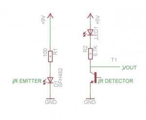
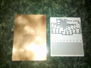
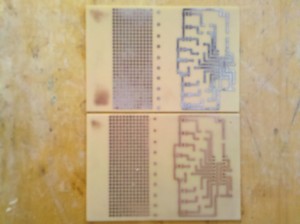
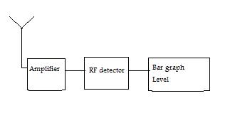
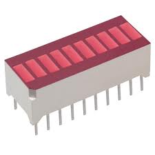
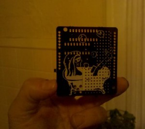
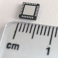
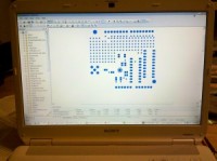
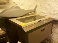
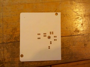
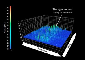
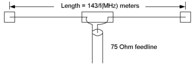
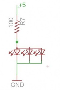
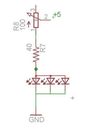
    UPDATE: I have been officially accepted to Maker Faire Bay Area! I will be exhibiting the Texting Trapper, which is the cell phone signal detection circuit I’ve been blogging about. SOOOO excited!

    The posts will return to all things geek early April.
    I’m traveling in Switzerland with my husband and partner Ollie. We’re visiting his family for about 10 days.
    We arrive on Friday in Zurich : first, shopping in the Airport mall for birthday presents, wine and such. We rent a car from Budget and get ripped off for GPS ($30 USD/day!) which is a crappy TomTom with old maps.

    UPDATE: I’ve just learned that the reason my phone’s GPS does not work is because it’s a Google Maps GPS. Google Maps works by storing the map in the Cloud, while TomTom works by storing the map locally. If there is no Cloud access due to a mismatch in phone communication technologies, you can download an app to turn the phone into a local GPS.

    Immediately after leaving the airport we make a quick stop, a Sales meeting for one of my day jobs at a laser company. After this, we drive around for awhile looking for a hotel…Switzerland is very expensive! We settle on a cheaper one, next door to IKEA. We find out later that all the relatives are laughing at us because we chose a hotel famous for having a secret underground parking lot for men and their hookers.

    Breakfast Saturday morning at the IKEA hotel is typical for Switzerland. Bread, an assortment of cheeses, an assortment of meats, muesli, yogurt, coffee. Very nice.

    Saturday is our Grosi’s (Grandmother) 90th birthday. There is a dinner party at Gasthaus Bären, which is a restaurant with a whole bunch of extra forks and spoons and glasses. In the USA this is called a 5-star. I am so jetlagged I fall asleep at the table after dessert. The elders outlast me by a couple of hours.

    After Sunday breakfast, a repeat of Saturday’s menu, I’ve eaten so much cheese I’m over it.

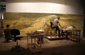
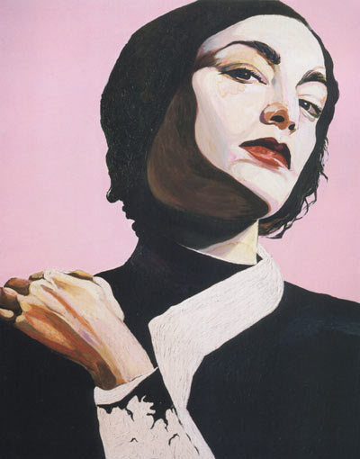
    We spend Sunday in Burgdorf. We go to the museum of Frank Gertsch and see a guest exhibition from Cornelia Schleime. She is talented and her history of being a feminist rebel impresses me.

    Die Herrin, 2002, Cornelia Schleime

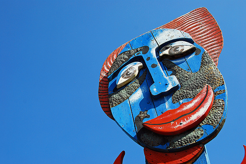
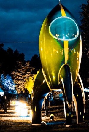
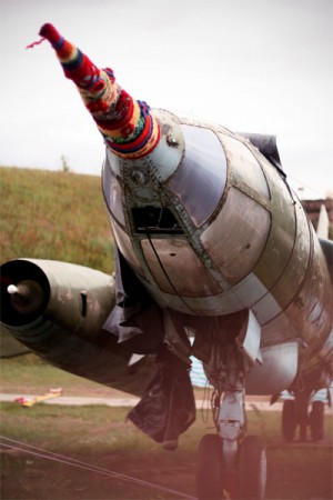
    After this, we visit another gallery, this time in an old meat slaughterhouse. The artist died in 2011, his name is Bernhard Luginbühl. His art is insane. There are Rube Goldberg-like pieces with switches on them to make balls roll around and clanky metal move from one side to the other. Plus cow heads!

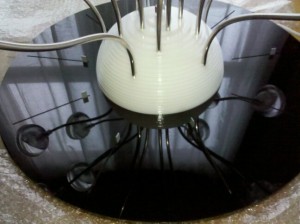
    Sunday dinner, another birthday, a cousin, 22: Fondue! I begin to fantasize about broccoli, but am distracted by cheesecake for dessert.

    Sunday night we stay with relatives, artists. Sylvia makes Tiefdruck, prints made from steamrollering patterns. Ueli (a name I only hear in Switzerland) is a Marketing exec who works for Baumann, a large and creative Swiss textiles company. Ueli is also a painter and is showing in Liepzig, Germany in a few weeks.

    Breakfast Monday morning: I cannot eat. Coffee.
    By lunchtime I am hungry and crabby. We stop at a little mountain store on the way to a hike. They have an amazing assortment of breads and cheeses. Hm. Why is everyone here so thin when all there is to eat is cheese and chocolate?

    The hike is beautiful, the mountains amazing. Dinner: more bread and cheese. With wine. YEAH!

    Tuesday morning we head to Stuttgart, Germany. We stay in a cheap hotel that is located next to a car painting place…they spray, we shut the windows and go to the Porsche museum.
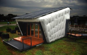
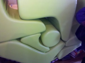
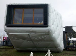
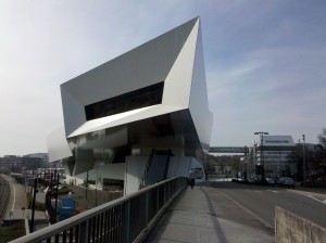
    The Porsche museum is completely lush, with drool-worthy cars and some interesting architecture.

    Porsche museum designed by Architects Delugan Meissl Associated

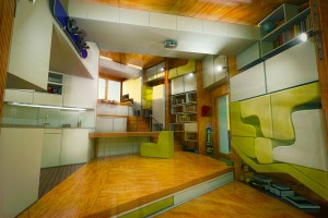
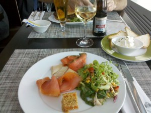
    We eat lunch in the museum restaurant looking out into the building. I could cry because it is so pretty and I am here in this amazing place, eating smoked fish and drinking such good wine.

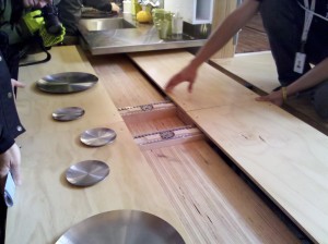
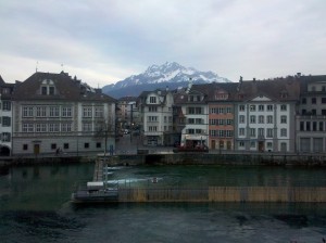
    We return to Switzerland on Thursday night to stay with one of Ollie’s cousins. We wander around Luzern, a beautiful city. We visit the place where she works, a showroom of stylish furniture. I posted some furniture photos on Google+
    Friday we hike up Mt. Pilatus, it is great to hike again since all of this cheese and bread is chubbifying. Mt. Pilatus…WOW!

    Luzern

    We spend Saturday night in Burgdorf, a family party and then go to a “Private Club” with some of the guests. The Private Club is private because you can smoke inside (like in the 80s) and we are all happy with wine.

    Thanks for reading “My Summer Vacation” – 🙂

  • Cell phone signal detection part 6

    For the purposes of my project I am defining cell phone signal detection as a change in power level sensed at the frequency of the cell phone. I am not doing any decoding of signals and there is no jamming (although I fully support projects of this type), I am only detecting a very small signal.

    From searching online, I notice a common frequency among US-based cell phones- the 850MHz band and the 1900MHz band. Each cell phone company has its own special frequency to broadcast on. For example, (I read this at RF Solutions) Sprint Nextel channels are scattered between 806 to 821, and then 851 to 866MHz. So Verizon, AT&T etc. won’t be on the Sprint bands. Have something to add to this? Please comment below.

    As I’ve mentioned in the posts before this one, my circuit is based around the AD8363 from Analog Devices. I’ve learned in the past week or so that basing my circuit on this chip alone isn’t going to amplify the cell phone signal sufficiently (sensitivity) or do the frequency filtering for me (selectivity).

    I need to filter out FM Radio (up to ~140MHz) and TV broadcasting stations (~470MHZ and up to 806MHz). Using the AD8363 requires some filtering on the input, because the chip itself is capable of sensing from 50Hz up to 2.6GHz. On the low end, I put a basic high pass filter in series between the antenna and the input. This cuts off lower frequency signals below about 700MHz.
    Here’s a picture of a passive high pass filter. The R here represents the AD8363, which happens to be 50ohms. I know this because the datasheet told me so. The Vout is the filtered signal that goes into the RF detector. The RF detector has 2 RF inputs, one where the signal goes in and the other connected to ground.

    The formula for the capacitor is Frequency in Hz= 1/(2 × π × 50 × C). What this capacitor will actually do is reduce the power going into the AD8363 below the calculated frequency, rendering the AD8363 useless at those frequencies.
    One issue I have with this chip is that it will only detect to about -56dBm. The transmitted cell phone signal is actually about -60dBm or less. I also want my circuit to work from an 8′ distance so this requires an amplifier before the detector.

    SIDE NOTE: DBm is means the power ratio in decibels (dB) of the measured power referenced to one milliwatt (mW). I keep looking at this great table on Wikipedia to get a sense of what that means in real life. My phone actually has a reading of its own received signal power and it is in the -88dBm range!

    While visiting GigaHertz LLC last week, I had the opportunity to work with their spectrum analyzer. So I actually got to see what frequency my phone was working (about 840MHz) on as well as the transmitted power (-65dBm). Verizon phones apparently hop frequencies depending on location so it was fun to see what my phone was transmitting on in Pittsburgh.
    I neglected to take any photos of the spectrum analyzer’s screen, but I found something at 911 Dispatch that illustrates the idea.


    What you see with the spectrum analyzer is the frequency (x-axis) vs. amplitude (y-axis). This is exactly the tool needed to characterize the cell phone signal to be detected.

    This has been a really long post, so if you got this far, thanks for reading. At some point, I’ll talk about the amplifier that was selected (recommended by GigaHertz) and some of the different antennas I’ve been testing with. Oh, and how to cut the upper frequency off before it reaches Wifi (2.4GHz).

    Link to part 5 in this series
    Link to part 4 in this series
    Link to Diode Detector post
    Link to part 3 in this series
    Link to part 2 in this series
    Link to part 1 in this series

    This is a block diagram that shows the basics of the circuit:


  • Cell phone signal detection part 5 – learning from RF Rockstars

    This is a placeholder post, I am going to add to this brief post (graphs! math! antennas!) in the next day or so. So check back!

    I did want to report that I got a small mention in MAKE blog which was SUPER COOL.

    Last week, I visited GigaHertz LLC in Pittsburgh. They have been schooling me in the world of RF, and in many ways, encouraging me to keep going in a field that is occasionally kicking my ass. Luckily, I have no ego 😉

    I’ve also been learning a ton from Ed Nisley Tuesday nights at an electronics group meeting. He knows a lot about RF and is one of the quoted “naysayers” in one of my previous posts. Turns out, he was right. My first PCB spin was embarrassingly noisy. But…moving forward, I’m waiting now for the next 2 spins to return.

    I also have emailing a little with Noah Shibley, who did a similar project a few years ago. I really love how the Engineering-maker community is so willing to share information.

    OK- more later…


  • Cell phone signal detection part 4

    20 days until Spring! This has been the suckiest winter ever for snowboarding, I haven’t gone even once. It snowed today and I just didn’t feel like it.
    Instead I’ve been procrastinating with a Mindbands brainwave detector.

    Last week I re-spun my cell phone signal detector board in two different versions, both to include smaller traces on the QFN (easier to reflow without shorts!). One of the versions has a power supply right on the board, the other uses an Arduino. The new spin moves the LEDs out of the way so that they aren’t switching on and off right next to the detector part of the circuit.

    RF engineering is its own special brand of difficulty. At times I’m really discouraged, nothing seems to work and I don’t understand why.

    So while I’m waiting for my boards to arrive in mid-March, I’m re-reading the RF detector chip documentation from Analog Devices. My circuit is based on the AD8363 and that will certainly change. The chip is fairly expensive and the range is too wide. I’ve been looking at some Mini Circuits chips because they’re cheaper and have a smaller range. I’d really like to detect up to 2GHz, and not have my circuit blinking about and confused because of random Wifi in the neighborhood.

    You can think of an RF detector chip like a little power meter. It takes in RF signal on one end from the antenna’s output and gives out a DC voltage. The voltage is proportional to the received signal (Watts). Pretty cool. You can then take that DC voltage and “do stuff” with it.
    I’m running a bar graph with it, so the higher the voltage received, the higher the LEDs on the bar graph light up.


  • Soldering Surface Mount – QFN adventures

    I recently designed my first RF signal detector circuit and PCB layout. There’s all kinds of RF layout warnings out there.

    “It won’t work if you lay out your board wrong”
    “You’ll have to troubleshoot invisible wireless signals with no spectrum analyzer.”
    “How are you going to solder that itty bitty QFN package crucial to the design?”

    Telling me I can’t do something is sure to make me see it as a challenge.
    So I got a couple of experienced people to look over my layout, who encouraged me to make changes and I sent it out. It turns out that an RF layout is quite important, you can put unwanted inductances (signal strength suckers) and not enough ground shielding into your circuit, causing what you thought was a nice design to … well, not work.

    After my layout drama was resolved, I sent my Gerber files to Laen’s PCB service which cost me around $25 for 3 boards.
    The boards came back in a sparkly purple envelope, graded.

    Since the boards from Laen include silkscreen on both sides, I put a nice Lex Kravitz original drawing on the back of my board.

    There is a QFN-16 part on the front of the board. QFN stands for Quad-Flad No Leads. That means there are no leads to solder to as they are conveniently placed UNDER the chip like a chastity belt.

    This picture is of a 28-pin QFN.

    The only way to get at these leads is to reflow solder, or put solder paste onto the PCB and plop the part on top, hoping that the solder will find its way to the leads and not bridge or leave any leads out.
    So I put my newbie questions out into the Twitterverse.

    “What tools should I use for reflowing?”
    “What solderpaste and flux should I buy and from where?”

    Here is the reflow tool that was recommended.

    I bought all my flux and pb-free solder paste from SRA. They’re on the east coast (USA) and so am I, so the shipping time was fast, although they charged me $8.50 for a ton of paper packaging. So they get an “FAIL” for environmentalism. Not cool.

    My husband, Oliver Tanner is a 3D designer and mechanical prototype machinist, so he has all kinds of fun tools like a laser, lathe and CNCs (yes plural). Ollie offered to cut me a stencil on the laser. The idea here is that you cut a stencil, squeegee solder paste through the holes, put the part on top and reflow. This isn’t exactly how I did it sucessfully, but almost.

    Our first try was with Kapton 2″ tape.

    I found the Kapton difficult to work with, too sticky, too thin, not wide enough (my board is 2.3″ wide), so we tried cutting again with an Avery label.

    The cutting came out pretty well this time, and the Avery label, being 2x thicker than Kapton, peeled nicely, and by now I’d peeled a stencil on and off half a dozen times and was feeling like this was cake. The following is a fast-forward to the successful method through the first 4 tries of getting the part to land correctly.
    After squeegee-ing the solder paste through the holes, I placed my board on the griddle at 325 degrees F and let the solder flow. Note: At this time there is NO flux on the board at all. In fact, I cleaned the board with 90% alcohol using a Q-tip before putting the solder paste on.

    I then put another Avery stencil on the board and dripped some flux through the stencil and just on the solder paste. This was very difficult to do as flux is like water and just wants to go everywhere. I was getting a lot of bridging until I reduced by 4x as much flux as I thought I should use.
    I took the QFN-16 part and placed it gently on the area, lining up the unseen leads as best as I could. You can see a glint on the top of the chip of where the leads are, so it’s not totally blind. In the future, I will make the QFN leads on the PCB a bit longer so that there is a clearer placement.
    Then I put the board back onto the griddle at 350F and waited about 5 minutes to remove the board.
    It did take 4 tries, but after checking connectivity on all 16 pins, this one was down.

    The real proof was after I hand soldered all of the 0805 (measures 0.08 by 0.05 inches) capacitors and resistors, the circuit works without getting hot or smoking or sadly refusing to accept power. YEAH!


  • Diode detector circuit for radio frequency signal detection

    Update: I am still building circuits that detect a cell phone signal.
    I’m only detecting that there is a signal, or the fact that there is current present. I’m not detecting what that signal actually means, decoded. That would be illegal.
    Update: it’s not going to be good as a kit design as the chips are too small to DIY, test versions will be available shortly.
    One college professor is looking forward to testing it on his classroom, and adding directional features and a water gun to squirt offenders. FUN!
    Want to test it? Email me!

    A simple way to detect the presence of a signal is with a diode detector.
    A diode detector is just a high speed, low voltage drop diode with a capacitor on the end of it, going to an amplifier.
    Basically, a diode will rectify the signal, allowing current to pass through it in one direction and not the other. So the diode clips either the negative or the positive side of the wave. The remaining wave is amplified, and viola! you have detected a signal.

    When determining your antenna length, you need to know the length (m) of your wavelength. The wavelength is the distance your radio wave travels for one cycle.
    The relationship between wavelength, speed of light and frequency contains these formulas:

    wavelength (m) = 300,000,000 / frequency (Hz) or approximately:
    wavelength in cm = 30,000 / frequency in MHz

    Note: the 300,000,000 is really 299792458 metres per second, or the speed of light


  • Cell phone signal detection part 3

    High frequency signals are so mysterious! How to design PCBs around them, how to detect the signal, how to usefully process…
    I’ve ordered some building block parts to string together a detection circuit in the 700MHz to 2.8GHz frequency range. I’m starting with an evaluation board from Analog Devices.
    I decided to go with an evaluation board because I’ve heard all sorts of dire warnings about board layouts making your circuits not work. On every chip manufacturer site (ie: Analog, Maxim etc.) there is a nice tutorial about PCB layout for RF PCBs.
    I also ordered a quad band antenna from Spark Fun, which I’ll try and directly couple to the eval board. If the signal is too low, I’ve ordered an RF amplifier to raise it up.
    I’m excited! Stay tuned…

    Link to the first post in this series
    Link to the second post in this series

  • Cell phone signal detection part 2

    From some of the emails I’ve gotten, and recent conversations I’ve had, it is clear that many of us are curious about how to characterize, decode or simply identify the level of cell phone signal power/radiation.

    Wikipedia says typical cell phone transmission power is in the 125mW to 500mW range.
    I grabbed this picture from Peter Cochrane’s blog to illustrate how small of a signal this is.


    The circuit I’m working on simply detects (a power level) when a call, text or email is made.
    It uses an antenna to detect the signal, which attaches to an RF detector to output a power level. Basically these chips are little power meters. Unfortunately, they are only available in surface mount which is a total pain in the ass for prototyping, and even more annoying for designing an easy to assemble kit.
    Most of the RF detectors go to an input level of -60dBm, which means an amplifier will be required in between the antenna and the RF detector. Typical opamps don’t have the required frequency response, so a specialized RF amplifier is the type of amplifier needed.

    A huge shout-out to Analog Devices for their help in understanding these concepts. They also have some really informative presentations on their site.
    Linear Technologies has some great information as well as having a super easy sample policy. My itty bitty chips just arrived, for free, via Fedex. Thanks Linear!

    RF “stuff” is really, really interesting to me. I think this is because the signals are truly invisible (to me) because I don’t have the tools needed to “see” what is going on. Other kinds of invisible signals can easily be viewed on an oscilloscope, even though understanding what is seen is another story 😉

    Signal Hound’s Spectrum Analyzer : WANT!

    See the post before this one: Cell phone signal detection part 1
    Link to the third post in this series

  • Cell phone signal detector part 1

    I’ve been building circuits to detect a cell phone signal.
    I use Verizon service for my smartphone that runs on the 3G network. 3G by the way, stands for 3rd generation, 1st gen being analog, and the 2nd being PCS.
    Verizon uses the 800 and 1900MHz frequency band for the 3G network.

    The basic concept of a cell phone signal detection circuit is to design your antenna to “catch” the right frequency. The signal is then amplified through a standard opAmp like the LM324. On the output of the opAmp, I use a Radio Shack variety BJT transistor in these circuits to amplify the voltage enough to light an LED.

    It is challenging to detect the signal strength without interference from noise. I have a Droid One and it is receiving signal in the -80dBm range, which corresponds to 10 pW. On my phone, I go to Settings, then Status – the received signal strength in dBm is located there. There’s unfortunately no place to read strength of transmitted signal.
    Link to dBm to Watts chart.

    This image is from Wikipedia’s Dipole antenna page


    Sounds simple, right?
    Except that the cell phone doesn’t always give off a signal. Mine (and presumably others in the Verizon 3G network) gives an easily detectable signal when I first make a call or am about to receive a call. When the 3G icon on my phone flickers, so does my LED.
    But unfortunately, when I’m talking on the phone or texting or using the internet, no easily detectable signal.

    Link to the second post in this series
    Link to the third post in this series


  • Hello world!

    Welcome to WordPress. This is your first post. Edit or delete it, then start blogging!

  • Solar Decathlon, Washington DC

    It’s been a busy few weeks. Lots of traveling, Finowfurt, Black Rock City, New York City and last week to Washington, DC for the Solar Decathlon. The Solar Decathlon is an exhibition where 20 student teams compete in 9 categories centered around energy efficiency. I had been wanting to go to the Decathlon for the past couple of years, but always had a Lack of Energy, Job And No Time Off problem. This year I have manifested a Great Work Situation (more on that in a future post – Doing What You Love, 4/7 of the time).

    The Solar Decathlon was very interesting. Solar is getting to be fairly cheap (half the price of two years ago!), and I think of it as simply a space-needy power source with a ton of rules and regulations ostensibly for safety. I didn’t perceive the Decathlon as having a main focus on solar, either. All of the homes were solar-powered, but rather than being presented as innovative, it was a given (YEAH!).
    I was a bit bummed that there wasn’t a clear comparison about how much energy it takes to manufacture a solar panel and ship a solar panel versus how much energy the panel provides in its lifetime. Obviously the panel provides a bunch more energy, but how much more?

    A couple of the homes had electric heat pumps that took care of heating and cooling. I’m always interested in temperature controls (staying warm, particularly) and spent some time checking the heat pumps out. A heat pump basically moves air around with little energy because heat will move naturally from a high temperature to an area with a lower temperature. A heat pump has a valve in it that can reverse the flow of the air, allowing heating or cooling. Here’s a generic heat pump concept video directly from SRP’s website.

    Check it out (you’ll need Quicktime movie viewer):

    HEAT PUMP MOVIE

    My favorite home design was Caltech’s CHIP home.
    This photo shamelessly taken from the CHIP website


    There were some cool quirks within the home such as custom furniture that fit into the walls and Kinect-controlled lights.

    Custom furniture in the interior
    This photo also shamelessly taken from the CHIP website


    I loved this table


    Here’s a close up of the CHIP house

    Up next: as soon as I take possession of Far McKon’s spare Kinect, I’m gonna make something cool.

  • Signals and Systems, a Formulaic Design Approach to creating an Interactive Art piece

    Since my last post, I have been to Burning Man, the Open Hardware Summit and World Maker Faire NYC.  All of those recent events were AWESOME and have been documented hugely online. However, this post is about Getting Started in creating an electronic or interactive piece.

    Daniel Rozin’s Wooden mirrors are my absolute favorite interactive artworks, taking an image input and translating this into a mirror output using many servo motors and a camera.


    Most interactive projects can be broken down into taking signals and translating them into a system or systems. If the project interacts with a person, then the signals are generated by the person and those signals make something move, shake, spin or react in some way.

    What exactly is a signal?

    We use the word signal in our everyday life when discussing traffic. Cars in the USA are required to have turn signals. These signals are generated by a person who wishes to show the nearby cars around that they will be turning left or right. This type of signal is passive, it merely shows the viewer information that may (or may not) trigger an action.

    An electrical definition: An impulse or a fluctuating electric quantity, such as voltage, current, or electric field strength, whose variations represent coded information.

    In the interactive projects that I design, I use electrical signals to generate a reaction in a system. An electrical signal is meaningless when it is released into the world without some kind of representation. Ever hear the philosophical riddle “If a tree falls in the forest and nobody hears it, does it make a sound?” That riddle can be applied to a signal…if a signal is generated, and nobody sees it, does it really exist?

    You can think of the signal and resulting system as an input and an output. It may be best to think about your output first. The output is your visual. It’s the thing that you and your audience will see.
    For example, I’m currently thinking about a large screen with a bunch of dancing avatars on it.
    For example, I’m currently thinking about walking through a smell forest. For example, I’m currently thinking about projecting your face on a weather balloon 50′ up. Or come to think of it, it would look way cooler if I projected you and your friends’ faces on multiple weather balloons….

    You get the idea.

    Once you’ve determined your visual, it’s time to think about your input signal, your trigger.
    Your input signal should relate in some way to your output system. You don’t want to use a slow trigger like barometric pressure to trigger fast moving outputs like a film. Otherwise you will be stuck staring at the same image for a really long time. On the other hand, using barometric pressure would be a perfect match for a dimmer switch on a light. You also need to pick an input that you can capture. It’s no good deciding you’ll capture the smell of bacon input and use that to turn on a microwave unless you know how to isolate the smell of bacon! Luckily, there are tons of sensors available to capture many things. And if it isn’t available and you really, really want it, you can design your own sensor or collaborate with a willing scientist to make it happen. I mean, who doesn’t want to trigger off the smell of bacon? I can’t believe there isn’t already a sensor available???

    Once you’ve determined your output and then your input and you are absolutely sure that a sensor exists to determine your input, it’s pretty electrical or mechanical from here. You will need to design your input sensor into a circuit and use it to switch the output.

    Super fun!
    Let me know
    how your project turns out!


  • Grand Rapids Art Prize

    From Ran Ortner, winner of the Grand Rapids Art Prize 2009.
    … if I ever encounter a young artist who has any doubts about investing the next ten years of his or her life in his or her work, my advice is always to quit. If you have any capacity to quit whatsoever, most certainly do yourself an enormous favor and quit. If you have no capacity whatsoever to quit, and you’ve tried a million times, in a million different ways, and you still can’t quit, then you know it’s right for you. Look at examples, historically, when art has been forbidden, when people have been incarcerated and had limited capacity—they still found a way. It’s in us and it is of us. You can’t extinguish it. The buoyant aspect of who we are is large and insistent.

  • Chaos Communication Camp recap

    Last week I visited Finowfurt near Berlin, Germany, Europe, Earth, Milky Way, Universe for the Chaos Communication Camp conference.
    The conference was billed as a conference for Hackers and Associated Life Forms. This photo, taken by Jake Blau, is of a rocket sculpture in the center.


    The talks included everything from DIY solar to e-waste to how to avoid having your Whole Identity Stolen by hackers. Workshops included RFID hacking, sushi making and building the TV-B-Gone.
    There was tons of conversation about Social Engineering and quitting your job to do what you love.
    I’m a big fan of the sport of Hardware Hacking and also thought there might be something there to learn about RF communications, so I went. I was also able to Social Engineer my way in with no ticket…YEAH!

    This conference was a camping conference, with lots of big weather-proof tents and the talks set up in hangars. At night everything was lit up with creative LED blinkie-ness.


    Since it was raining, I camped under a plane. Notice the knitting bomb that someone kindly left for us to enjoy!


    The badges were the coolest I’ve ever experienced. You could update the firmware on them and get games. And they text messaged with people nearby. Someone attached a Geiger counter to communicate with their badge. Geiger counters have lately, in my opinion, gotten far too popular….the tubes are now too expensive and difficult to source. Grrrr.


    Some of the people I met were Hao Zhang, who is organizing a Hacker event in Beijing next April and looking for hackers to exhibit, attend and give workshops. I met the inventor Jimmie P. Rodgers, who makes the LoL shield for the Arduino. A couple of 3D printing projects were there MakerBot and RepRap. Mitch Altman is really smart and is a quit your job and do what you love evangelist.
    I also met various people from Hackerspaces in Berlin and Vienna and hilariously, in New York City.
    A great trip…I highly recommend it, the next one takes place in 2015.

  • Workshop Babble

    Every Maker or Engineer needs some kind of workshop to create in.
    In 1994 I rented a barn on the property of a friend’s rental in Olympia, WA. The barn was awesome, with a high ceiling and huge doors that opened up to the outside. In October, when we arrived, it was warm outside. In January, the owner of the huge barn doors removed them from the barn and took them away. I was really into making sculptural hats at the time and I needed my fingers to sew. Brrrr.

    In 1995, Tucson, AZ, I bought cubicle dividers and put them up in our kitchen to create some workspace. My good friend and roommate Andrea would call over the cube and ask me if I wanted some stirfry. At that time in my life, I was deeply involved in fish tank building, specifically from junked stainless steel wood stove pipes. The tanks were modular, each tank holding just one Fighting Fish. They plugged into each other to make different shapes.
    We ran out of space within the month and moved to a more spacious palace in another neighborhood. People would knock on the gate outside our house asking for drugs and money. The upside was that the rent was so cheap I got an entire room to myself to work in.

    In 1996, I moved back home to NY and rented a barn in New Paltz. This barn had a propane heater with a blower and a door with a key. At this time I was doing a lot of silver-smithing, a craft that I pursued seriously for several years. I kept this space until the heater broke.

    I moved my workshop to Kingston, NY in 1997. This was a glorious space, a 1200 square foot ground floor space with wood floors and big windows. And super cheap, because the building was for sale. I split the space with Alex Hamilton, one of the most creative people I’ve ever met in my life. I started getting into animatronics in a big way, building remote control bat wings and puppets with multiple motion eyeballs.

    When the Kingston building got sold in 1998, I moved to Manhattan and briefly tried to work out of my 9′ x 9′ bedroom, kicking the dog, Kyote, out whenever I needed to spray glue. Within a couple of months, it was clear I’d need to rent another space. I lucked out, sharing a space with Kelly Gleason and Robert Perez in Dennis Oppenheim’s (who died recently but is alive on Facebook, WEIRD) building on Franklin street. Kelly was a Special FX makeup artist and she had crazy jobs coming in all the time. She’d hire me to make gallons of blood, a burnt replica of that guy in 90210, an exploding head. Robert is a photographer who shoots primarily glamour shots- gorgeous photos of women without much clothing on. I’d come to work in the studio and there would be half a dozen naked girls sitting around in one room and severed body parts in another.
    I loved that studio and stayed there for 5 years.

    Now I have a space in Kingston, NY again. I’ve had the same workshop since 2002.
    Here’s a candid shot of my workbench.


    Every engineer needs to have a whiteboard…and a blond wig!


  • Shutter Glass Dress

    Shutter glass goes opaque when current is applied, and clear when there is none. I grabbed the following gif from Liquid Crystal Technologies.


    I had the cost of 100 1″ x 3″ pieces estimated and it was in the $4,000 range. Sigh. Since this material is essentially glass, the material is fairly stiff, even in the flexible form.
    You can apply an analog voltage to this, essentially being able to make this glass any color between clear and black. I would like to make a dress out of this type of material.
    Just imagine a little black dress that turns transparent!

  • Microprocessor-driven relay

    Problem: I have a 12VDC fan that needs to be switched on and off. It’s a pretty windy fan with an Endless Breeze label on it, claims to be 900CFM and uses 36Watts.

    Problem: I’m using a microprocessor (PIC16F877A if you must know) to switch the fan on and off.

    The fan needs about 3A to switch. The microprocessor isn’t capable of sourcing or sinking very much current, only about 25mA, which is not even close to what the fan needs.

    Here’s a quick sketch of what the pin of the microprocessor connects to. Since the relay coil needs 400mW to energize, at 5V, that’s 80mA needed. Notice there is a flyback diode in my sketch. You always need that, otherwise when the relay switches off, current can come back into the circuit and let the magic smoke out of something.

    Here’s a standard circuit of a BJT transistor switch:

    Rc is the resistance of the relay coil (62ohms) so the current flowing through the coil will be 5V/62ohms = 80mA.
    When you choose your transistor, there is a specification called hFE , which is the current gain of that particular transistor. I suppose a bigger gain is better, but I’m just going to use what I have lying around and hope it’s enough.
    I have a 2924 NPN transistor, and the hFE is 100. Therefore, I need to have 0.8mA minimum to switch the relay coil. The microprocessor can easily do this, so I am happy. Rb maximum should be 6.25k (5V/0.8mA). If I go a little smaller, that will be OK too, since it would be good if there is extra current in case the hFE isn’t exactly 100.

    Here’s the circuit. Email me if you have any questions!


  • Theo Jansen’s Strandbeest

    This…you have got to see.

    .

  • Kickstarter = inventor funding

    Kickstarter is a micro-investing website where you can post a project and ask the online world (and your friends and family) for funding.
    The project you post has to be a “doing” project. Kickstarter doesn’t accept “fund my life” fundraisers.
    Some of the projects asking for funding are Product Design projects. This is great because you can do your market research while you ask for backers. If the Product Design project isn’t backed, it could be a conclusion that it is unlikely to sell. Every project offers backer rewards. Many of the Product Design projects offer a first run of the product.
    Better to find out that the world outside your head doesn’t want to buy it before you invest a lot of time and money into engineering and manufacturing it.

    I just backed this project: an Upstate NY artist, Zac Shavrick, is making steel sculptures of people. Weird, monster-y sculptures. YEAH! I love it!


  • Pianococktail – a piano that plays drinks!

    I have only seen the Pianococktail once, at an ITP student show (2008) at NYU, in New York City.
    It is a piano whose keys actuate solenoids that open valves to bottles containing drink mixtures, Red Bull, alcohol and soda.
    Whatever song you play will mix its own special drink.
    I’ve always thought this was one of the most innovative pieces I’ve ever seen and have never forgotten it. I Googled the artist, Geraldine Schenkel today, and was disappointed to find little information on her. The Piano Cocktail site is in French, but Google Translate takes care of that if you don’t speak it.

    Here’s a little (translated) blurb from the site:
    The pianocoktail is a bar above all: that the pianist plays, it is necessary that people drink. The piano does the rest. A trill in a position to mix the rum syrup, cane sugar and the dose of tequila will be discharged by an F sharp.
    Each has its own cocktail music: you choose an alcohol. Or melody … (see menu) and passes control to the pianist.
    There are non-alcoholic cocktails for children and pregnant women.
    And for the purposes of the evening, you can taste the coffin: a gutter that gets the wrong notes, stray bullets, lost doses of vodka and ginger juice spurts …

    Here’s a video:


  • A Watt is not a Watt, What?

    I’ve just started to work with sound for the first time. Oh, I’ve dabbled a little bit in the record-able birthday card arena, built a couple of embedded amplifiers and a filter (strong word for a capacitor) or two, but I’m pretty clueless when it comes to the sound lingo.

    The HeartBeat Dome project requires two speakers, one that runs all the time and the other that spits out heartbeats. My project partner Lex found this perfectly sized (4″ diameter, 8″ length) speaker on eBay to run the all-the-time sound.

    speaker aker

    The speaker’s specifications say 25 Watt Peak Power Output.
    As an electrical person, I took this spec to mean Maximum power output 25 Watts at full volume.
    I have no idea what 25 Watts sounds like, but Lex reminded me how loud his high school band was with a 40 Watt amplifier.
    Since I am doing some power supply design that encompasses all the speakers, it is necessary to know exactly how much power the speaker consumes.
    So I plug the AC to DC converter wall wart into the power strip and from the DC side of the wall wart, I measure 9.5 Volts and something like 250 mA. Which V*A = just under 3 Watts input. Hm. Confusion. Really? You can put 3 Watts in and get 25 watts out? Further research shows there is a battery inside the speaker, so without the AC wall wart using up all the power, the battery can theoretically at optimal condition, put out 2A / 7.5V. Still, this is 15 Watts…not the advertised 25.

    So I write to the company and get this back:

    Dear Sophi,
    The power is described as the peak output power 25 watts. If we just
    calculate the power by volts and the current, then it cannot be
    25watts. What’s more, our techinican also specified about the power. I
    once have told him about this issue, it can be explained as the above.
    Have a nice week.
    Best regards,
    XXX

    OK…now I’m annoyed. Is it possible that Electrical Watts are different than Audio Watts?
    I’m sure you all know the answer to this. A unit is a definition. So all Watts are Watts.
    Electrical Watts are quite easy to calculate, but Audio Watts less so.

    I grabbed the following awesome example from Crown Audio.

    Example: You are designing a system where the farthest listening position from the loudspeaker is 100 meters, and the desired Sound Pressure Level is 85 dB SPL The loudspeaker chosen for the job has a sensitivity rating of 95 dB. With the minimum recommended amplifier headroom of 3 dB, then you need to choose an amplifier that can supply at least 1,995 watts to the loudspeaker.

    Equations used to calculate the data:

    dBW = Lreq – Lsens + 20 * Log (D2/Dref) + HR

    W = 10 to the power of (dBW / 10)

    Where:
    Lreq = required SPL at listener
    Lsens = loudspeaker sensitivity (1W/1M)
    D2 = loudspeaker-to-listener distance
    Dref = reference distance
    HR = desired amplifier headroom
    dBW = ratio of power referenced to 1 watt
    W = power required

    So moving forward, I have another speaker, a subwoofer-amplifier-powered deal that is about 1.5 cubic feet and rated at 80 Watts. I go through the same routine again, measuring the voltage and current input. I get just about 35 Watts input. The input power is related to how loud my signal is. I ask a friend to record me something at an insanely loud amplitude but I can’t get the input power over 43 Watts.

    sub

    I’m guessing these specs are a marketing trick by people who are math clueless. And if you really can get more power out of an audio amplifier than you put in, Global Energy Crisis= SOLVED!


  • HeartBeat Dome and the path to creativity

    It’s time for a new project again. The new project will be designed for Burning man Festival in Black Rock City, Nevada. I’m working with three other people on this one, and it’s working out really well. Two of the people live 3,000 miles away from me so designing something over email and texting is a new experience for me. Working virtually really focuses things because everything important is written down and we don’t spend so much time “hanging out” instead of working.

    The project is called HeartBeat Dome and it triggers on your own heartbeat. The concept is cool because hey, everyone has a heartbeat, which means that everyone can relate to it.
    Here’s the link for a formal description and a couple of images of the proposed HeartBeat Dome.

    Many conversations center around what is creativity and how to get more of it. I define creativity as an unusual way of solving a problem. The problem can be as basic as making a peanut butter and jelly sandwich or as esoteric as “what am I going to create?”. This last (very difficult) question encompasses the whole universe since nothing is impossible and you’re only limited by your own mind.
    There is a lot less need for creativity when you have limits.
    Take the peanut butter and jelly sandwich for example. By definition, there are only three ingredients. The only choices are choosing the brand and type of peanut butter (organic? smooth? added sugar?), jelly (strawberry? apricot?) and bread (toasted? grain? Wonder?).
    If you want that sandwich right now, you are further limited by what is available in the immediate area.

    PB&J

    So how do you answer more difficult questions? Creativity is by no means limited to things that fall in the artistic range. For example, creativity is used to solve medical, mathematical and all different kinds of problems.
    How do you cure cancer? How do you grow longer eyelashes? How do you write a mathematical algorithm that will do your taxes? What about writing a Smart phone app?
    All of those things need creativity, out of the box thinking, the ability to grab a problem and solve it with undefined things.
    I went searching online for what defines a creative person and found many discussions of this topic. The reason that it is so important is because there are always new problems to be solved, in business, in life, in art. The world needs creativity to move forward.

    So how do you get more of it? Here is a little bit about my process.

    My creative process is typically to think of the problem and work backwards to solve it. I’ll come up with the vision, as complicated as my imagination wants it to be. I don’t get sucked into negativity as in “that won’t work, that’s too hard, that will cost too much money”. Those are details that hamper my creativity personally. I might have the capacity to dream up a Giraffe petting zoo, but that doesn’t mean I can or need to make it happen.

    Visualization without limits trains your mind to be more creative!

    Once I have the vision hammered out, I’ll write in words a summary of what it is. Then it’s time for details. And I’m not afraid or too prideful to give up on something before it gets started. Why work on something that isn’t going to be fun to work on?
    Creativity takes practice. One of my uncles wrote a book called the ABCs of Business and it has this great advice of taking a walk every morning for 2 hours. No iPod, no dog, no companion. When you are truly alone, you focus your mind entirely. I had never even considered doing this before I read his book, but now I try to do this every morning for 25 minutes. It really helps.

    What if you crave creativity but have gotten comfortable with the Peanut Butter and Jelly sandwich limits? Narrow down your choices. If it’s a building project and it requires paint, make it require only one choice, warm color or cool color. Ultimately it matters more that you do it than what decision you make.

    There is also a lot to be said for Getting ‘Er Done. Coming up with visions, ideas and plans takes a lot of effort. I have gotten really comfortable with failure, a byproduct of coming up with big ideas and plans.
    I have the occasional month or two where I’m just not feeling it. I get through those times by pretending that I do feel it. Fake it til you Make it is the best advice I have for anyone trying to jumpstart their own creativity.


  • Finger Pulse Oximeter!

    Check back for more posts on the Oximeter. Here’s the link for the Maker Faire recap.
    I ordered a finger pulse oximeter online, which was waiting for me on my porch when I got home yesterday.

    oximeter working

    A pulse oximeter measures a couple of important human body functions- the heart rate and hemoglobin oxygen saturation. Heart rate monitoring is important for heart problem detection, and oxygen saturation levels can indicate respiratory problems. For the record, a normal resting heart beat is between 60 and 100 beats per minute… a heart beat on the low end of normal indicates an efficiently running heart. A normal hemoglobin oxygen saturation percentage is between 95 and 100%. Simply put, this means how easily does hemoglobin transfer oxygen molecules into and out of its surrounding fluid.

    Want to know more about this?

    Ox

    The way this Oximeter works is really interesting. There are two LEDs, each sending out light of differing wavelengths, facing a photodiode (converts light to current). You put your finger in between the LED and the photodiode.
    The blood vessels expand and contract with each heartbeat, and the pertinent signal bounces in time, allowing the heart rate to be calculated. The oxyhemoglobin ratio is calculated from the absorption of the light ratio of the two differing wavelengths.
    Of course I had to open it up.

    v

    And then a little more.

    v

    So it’s now broken since I unfortunately snapped the ribbon cable keeping the two halves together. Even though I soldered it back together, it will only power on and does not work anymore 🙁
    It is powered by a STM32F103C8T6 with a 8MHz crystal.
    …I just ordered two more.


  • Maker Faire Recap

    This past weekend Ollie and I exhibited at Maker Faire in San Francisco.
    mf

    Many of my favorite organizations were there, Exploratorium, Spark Fun, Digikey, Lego, Etsy, Instructables, Google, NASA (!!!)…. and many smaller individuals who haven’t yet grown into largeish organizations, MaceTech, Ira Sherman (chastity belts!!!), Sensebridge, Mark Lottor.

    Setup was very easy- we shipped three gigantic boxes directly to Maker Faire. Our booth contained only three pieces, 2 radiation detectors and a new piece that has an analog lighting control that I’ve been writing about recently. Arduino-free artwork!

    ear lamp 1

    ear 2

    ear

    The organizers of Maker Faire treated the Makers awesomely. Check out the Paella that was provided for us.
    paella

    Here are some of the highlights.
    Sally Ng is an Industrial designer who has won a bunch of design awards. I was really impressed with these portion control plates, both with the concept and with the execution. She has them in a red color, but they were stolen from her last show. Sort of a double edged compliment I think.
    Sally Ng

    sn

    I unfortunately didn’t get a chance to hang out at the Google (blog link here) area. They were showing off their SketchUp software and the Android software development kit. I heard something about self driving cars, which hopefully they will be ready to show soon!
    google

    Arc Attack is a Tesla Coil performance that incorporates music and light. It’s really fun to watch…. once or twice. We were placed right next to the stage where the performance happened six times a day. The result was that we got a ton of traffic (thank you Arc Attack!), but it was also loud!
    arcattack

    Erik Larson stopped by our booth. He designs CymaScopes. This is a type of scientific instrumentation that make sound waves visible in water. I had never seen this kind of instrument before and I am blown away by the gorgeousness of the results. I only saw pictures on Erik’s phone and I plan to find somewhere to view this in real life ASAP. Here are some pictures that I snagged from the company’s website.
    erik larson

    erik larson

    We visited the Exploratorium museum while I was in San Francisco. The exhibits were cool, but they saved the coolest ones for Maker Faire. One of the best pieces they showed is called Harmony Swingset, a prototype by Earl Stirling. The lengths of the swings are cut so that they are harmonically tuned to each other. When people swing on them, it looks like a wave going down the line. A video shows this best …flash forward to 1:35.


    My friend Brian Malovany was there with his Lego Van. I went to visit him once during the show and he was mobbed with children.
    Lego Van

    I will close this post with a photo of a sign with a partial quote from Barack Obama’s Inaugural address.
    Here’s a link to the full speech.

    sign


  • 555 timer lighting controls and a wee bit of silicone casting

    I am not so confident about my newest project. For one thing, it encompasses a number of unrelated processes, all of which have a failure factor. Mold making, casting, laser cutting, tube bending and of course circuit design.

    The concept is that there is a stepped white acrylic base, with stainless steel tubing coming out in all directions like flower stems. The flowers sit atop the stainless steel tubing and are clear silicone castings with LEDs inside them. The LEDs change colors by way of slider switch controls.

    I am writing this while listening to my silicone de-gass in the vacuum bell jar. The silicone was manufactured at Silicones Inc. and I am not familiar with it, so I am going to get unexpected results. The silicone is water-clear and Andre, the silicone distributor I use tells me one of his customers made a gigantic bullet (!!) and shone lights through it.
    Silicones Inc. was nice enough to send me 12 pounds of sample material, 6 pounds each of XP-536 V22 and V23. Which makes me wonder what the other 21 Versions were like. I’m not even sure if they sell the XP-536 regularly because a batch was mixed in the lab to ship to me.
    I’m casting tonight, so in about 30 hours I will know if I like the product or not (30 hour cure time, which is unusually long). UPDATE: LOVE THE SILICONE!!
    sil

    I spent the day soldering a lighting controller circuit board. No software!
    The circuit has 9 slider switches, 15 LEDs, 3 555 timers and 3 556 timers (2 555s in one package). Also a bunch of resistors and capacitors.
    Here’s the schematic in Google docs format
    Email me if you want a better copy.


  • CLEO conference – lasers are cool

    Last week I worked at the CLEO conference in Baltimore, Maryland. It was a fun week- it was nice and sunny, I got a stylee ride both ways (one way in Diesel Jetta & the other in Nissan Hybrid) and ate some really good seafood.
    The CLEO conference is a trade show and conference about lasers and optics. When I think about lasers I remember Pink Floyd concerts at the planetarium in New York City. Laser facials, hair removal, light pens. Pretty and prettifying.
    The lasers shown at this conference are used in some really interesting applications.
    Daylight Solutions was showing how they use lasers to detect chemical agents in the air. A doctor might use one of their lasers to look at one’s breath and then analyze it for healthful or unhealthful components. Think reeeeeally expensive breathalyzer test.
    Some of the lasers are high power and short pulse, which creates a lot of energy for cutting and also high precision. IMRA has femtosecond lasers which means that they pulse at one quadrillionth of a second!! The shorter the pulse, the more accurate the cut and that is why this type of laser is used in laser eye surgery.
    My favorite booth was Thorlabs. Thorlabs sells pretty much everything to do with optics holders, accessories, motion control and some other stuff I’ve never seen before. They had a really nice booth setup with lots of helpful and smart people who showed me everything until my brain hurt.
    Shown below is their awesome logo before the logo is optimized with one of their lenses.

    dog


  • Analog lighting control and the LED

    Do you have dimmer switches on your incandescent lights?
    They used to be basically a resistor that controls the current going to the filament in your bulb. The filament is the little coiled wire inside of the bulb. As current is put into the filament, it is released as heat. When a wire gets really hot, it turns red. This is what you’re seeing when you turn on an incandescent.
    As you turn the dimmer switch (think potentiometer), the current going to the filament is reduced and the light gets less hot and dimmer. Or the current is increased as the potentiometer decreases in value and the light gets hotter and brighter.


    According to How Stuff Works, the new and improved way is to pulse power to the filament, using the sine wave characteristic of AC power to switch the current on and off. It’s a great article … I love How Stuff Works!

    LEDs can’t really be controlled in the same way, unfortunately. The reason for this is that they are not a resistive device. The incandescent bulb uses heat to make light, but an LED that gets too hot will just die.
    There is a limit to its brightness.
    Here’s a super simple circuit to illustrate what I mean. There are three LEDs there because it is a RGB in one package. That means there is a red, a blue and a green LED all in the same circuit.
    pp
    This circuit is designed for about 20 mA, which is what the LED specifications say. If you run more than 20 mA through the LED continuously, the LED will get hot and die.

    So I’m going to cheat a little bit, run more than 20 mA through the LED but limit it with this circuit. I’ll use the potentiometer to turn the amount of current up or down. The big problem with this circuit is that you can’t turn the LED OFF. Even if you did turn it off by making the resistance very very high, a potentiometer in the Mohm range is big and expensive.
    pot

    The solution is to pulse the current to the LED. While the current is on, the LED is on, and while it is off, the LED is off. While the LED is off it has a chance to cool down. However, the human eye keeps the image of the on LED for about a 25th of a second, which tricks the brain into thinking it is always on if the LED is pulsed at that rate or higher.


  • Bull and Buddha, Poughkeepsie, NY

    I decided to meet a friend tonight at Bull and Buddha in Poughkeepsie, NY.

    Look at these gorgeous lamps!
    L1

    lamp2

    YUMMY Menu!!

    menu

    And I love the Big Buddha behind the bar.

    buddha

  • Maker Faire – new project!

    I just found out that I am exhibiting at the Bay Area Maker Faire!
    I applied after the deadline and was accepted as a last-minute entry. So I will make something new to show and also bring a couple of 2010 pieces.
    The new thing that I am conceptualizing has something to do with software-less lighting controls and also something to do with ears. So the first thing is to go into my attic and see what EAR related supplies there are already.
    My attic has some pretty cool stuff stored in it. There are a few animatronic puppets, ice sculpture supplies, random motors and quite a few lifecasts of various body parts.

    s

    But I am only looking for ear molds. Luckily I find a silicone mold and cast an ear!
    The first casting comes out filthy and full of bubbles.

    ear

    Later on….
    ear


  • Felt sperm! (I’m sooooo mature)

    Hine Mizushima does some great original work…and this one cracked me up.

    felt sperm

  • Keepon robot helps autistic children

    I just saw this video of Keepon, a robot designed to help autistic children engage socially.
    It looks like an old style push button toy, but has 2 cameras (!!) in its head and a microphone in its nose. Awesome bonus: this video (@ 1:25) briefly shows off the mechanics that make Keepon interact.
    The second video shows Keepon dancing. It blows me away.


  • It’s all about the Make-cation

    My new friend Stephanie Alarcon coined the word Make-cation earlier today. Check out her blog, it rocks!
    The Make-cation is the vacation that you take from your regular life in order to make stuff!
    Making stuff can take a long time…. from thinking it up, to researching it, to screwing it up, to redoing it, to finishing it. My Make Desire can make me crazy if I don’t set aside time to take Make-cations.


  • Oscillating with the 74HC14

    Today, I built an oscillator with the 74HC14 hex inverter Schmitt trigger.
    Here’s the datasheet.
    I thought this was interesting, the inventor of the Schmitt trigger, Otto Herbert Schmitt (1913 – 1998), was a scientist who worked both in physics and biology. He figured out the trigger while studying neural impulse propagation in squid nerves.

    Pretty

    I built this circuit with a capacitor 0.01uF and resistor 14.8k, which were just lying on the bench. I calculate a frequency of about 6.75kHz. Freq (Hz) = 1/ (R*F)

    Which is pretty close to what shows on the oscilloscope … I’m looking at the output signal on pin 12.
    Time (seconds) = 1/Frequency (Hz)
    osc

    I then used all the gates available and made three oscillators. By using different values for R (Mohm range) and C (uF range) on each oscillator, and therefore creating three out of phase oscillators, I was able to get a nice color cycling effect on an RGB LED.
    osc


  • Open Source Hardware logo selected!

    Yesterday, the open source hardware logo designed by Macklin Chaffee was selected. Over 9000 people voted!
    From the OSHW definition, the principle is “Open source hardware is hardware whose design is made publicly available so that anyone can study, modify, distribute, make, and sell the design or hardware based on that design.”
    Yessssssss! Collaboration rocks my world.
    OSHW


  • Recycling the Metrocard

    Stephen Shaheen designed this bench made from Metrocards on a steel frame.
    Mr. Shaheen, I salute your imagination!
    Metrocard chair

  • The Folding Plug

    I ran across this super cool design today while looking at power strips.
    The folding plug from the UK based Made in M!nd folds to be 0.393″ thin!
    fold
    It will be released sometime this year with a product line designed around it … maybe some folding phone chargers?

  • Back to basics…the 74HC04

    I love blinky things and I love to think about how to design something a little differently.
    Probably the most common way to control red-green-blue LEDs is with a pulse width modulation signal from a microcontroller. Many coding interfaces have built in PWM functions so that you can be up and running within a few minutes or hours.

    But what if you don’t want to write software? Or you don’t want to deal with buying a whole other set of tools, programmer, microprocessor, cable… and then you have to download a compiler too. Instant gratification, NOT.

    All this just to make a blinky.

    I am making an RGB LED fader that can be controlled without software or a microprocessor.
    When you use a hex inverter of the 74 series, a 74C04, you can make it oscillate simply by tying the output to the input.

    Update: I couldn’t get the 74C04 to oscillate, but had great success with the 74HC14

    There are 6 inverters on my 74C04 chip, but an RGB LED only has 3 distinct LEDs in it.
    Here is what a “typical hex inverter oscillator” using 1 inverter looks like:
    f
    I’m going to run the 3 oscillators through an LED. Basically, I’m going to connect one end (the common anode) of the LED to the +Voltage and the other 3 pins (red, green, blue) through resistors to the outputs of the inverter.

    A small word about 4-pin common anode vs. common cathode LEDs:
    Be careful what you buy. If you buy the common cathode version, you need all of your control lines (red, green, blue) to be controlled by sourcing current. Since many LED drivers sink current it may be better to purchase a common anode RGB LED from which the control lines can be controlled from ground. I have 32 common cathode RGBs lying around. Sigh.


  • Voltage and Current RMS rambling

    An easy way to calculate the power needed to drive the speaker uses Paverage = VRMS * IRMS, or Paverage = Power (Watts) = Voltage squared/ Resistance (Ohms). This uses only the resistive part of the impedance.

    Watts RMS actually doesn’t exist. The voltage in the formula refers to RMS Voltage (explained below), but the calculated power is average power and it is called Watts.

    AC Voltage and Current cycles from 0 to the positive peak voltage, and back through 0 to the negative peak voltage. Since it isn’t accurate to get the voltage or current value by measuring AC Voltage at an instantaneous point, RMS is used as a way to define the effective value of an AC (changing with time) voltage or current.
    RMS is not the average, the average of an AC signal is zero because the negative and positive peaks cancel each other out.
    V RMS is = 0.7 * Vpeak
    Vpeak is = 1.4 * VRMS

    Here is a good way to picture it : A lamp connected to a 6 VDC shines with the same intensity as a lamp connected to a 6 VRMS supply. If you connect the lamp to a 6 Vpeak supply, then it is only getting 0.7 *6 VRMS = 4.2 VRMS (same as 4.2 VDC). This example came from here.

    A DVM shows VRMS values on the digital readout. This is useful because it makes a nice comparison to a DC Voltage such as for a battery.
    An oscilloscope shows the entire cycle, and exhibits the Voltage peaks, both negative and positive.


  • Loudspeaker ramblings

    I’ve never really thought too much about getting sound out into the world. Everything just…works. I have an old Samsung mp3 player, it plays music through speakers into my ear. I can adjust the volume easily.
    Same for my beloved Droid phone. It outputs both music and voices.

    Last summer I built something that ran off a 12 volt -12 amp-hour battery. The sound output was through an 8 ohm speaker. Not only was the sound not very loud, but the battery ran flat after 2 nights.
    Oops.

    I will take the opportunity for a do-over! I know- very exciting….SPEAKERS!!!! Amplifiers!!!! Noise!!!!
    A little research turned up the following: speech is at 60 dB, vacuum cleaners at 70 dB and a chainsaw is 110 dB.
    And over 192 dB can kill you. WTF????

    For what I’m doing, I’m OK with vacuum cleaner loudness, so I would design for 90 dB to give some space above what I need.

    In order to figure out my power calculation (so that I don’t end up with dead batteries this summer) I need to know what my power calculation in Watts is, as it relates to dB.
    Looks like I need about 4 – 8 Watts of power to run my speaker, depending on the type of speaker.

    A speaker isn’t completely a resistive load -the value of a speaker is measured in inductance, which varies with frequency and resistance. The impedance of the speaker is related to the frequency. The graph below illustrates an 8 ohm speaker as it relates to frequency. I think this graph is interesting. It clearly shows that 8 ohms is an average and the impedance of the “8 ohm” speaker is all over the map.

    amp