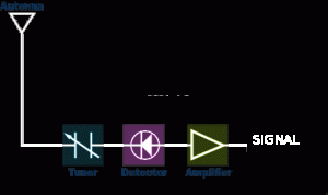
Diode detector circuit for radio frequency signal detection
Update: I am still building circuits that detect a cell phone signal.
I’m only detecting that there is a signal, or the fact that there is current present. I’m not detecting what that signal actually means, decoded. That would be illegal.
Update: it’s not going to be good as a kit design as the chips are too small to DIY, test versions will be available shortly.
One college professor is looking forward to testing it on his classroom, and adding directional features and a water gun to squirt offenders. FUN!
Want to test it? Email me!
A simple way to detect the presence of a signal is with a diode detector.
A diode detector is just a high speed, low voltage drop diode with a capacitor on the end of it, going to an amplifier.
Basically, a diode will rectify the signal, allowing current to pass through it in one direction and not the other. So the diode clips either the negative or the positive side of the wave. The remaining wave is amplified, and viola! you have detected a signal.

When determining your antenna length, you need to know the length (m) of your wavelength. The wavelength is the distance your radio wave travels for one cycle.
The relationship between wavelength, speed of light and frequency contains these formulas:
wavelength (m) = 300,000,000 / frequency (Hz) or approximately:
wavelength in cm = 30,000 / frequency in MHz
Note: the 300,000,000 is really 299792458 metres per second, or the speed of light